Finished dimpling the right elevator skin with the DRDT-2 and deburred the edges. Deburred and dimpled the counterweight skin, the stiffeners, and a couple of ribs.
I beveled the counterweight skin at the lap joint with the elevator skin as instructed in the manual. It wasn't obvious what the manual was asking me to do, so I dug up some posts on VAF. Basically it's just putting a notch in the counterweight skin so that the elevator skin will rest into it instead of laying entirely on top of it. I will also roll the elevator skin when my edge roller arrives. Upon reading further, I believe I'm actually supposed to taper the edge of the counterbalance skin so that it's not a sharp bump for the elevator skin to sit on. What I did doesn't hurt, but it's probably not necessary if the lap joint is rolled properly.
Trimmed the lead counterweight according to the diagram (though I can't seem to find a reference to do so in the manual). Used the drill press to drill a radius at the specified place and used the bandsaw to cut to the hole.
Spent some time reading ahead in the manual. I feel I'm getting close to "prime time". Can't wait to start riveting everything together. I bet it's going to go together very fast from then on.
Time spent: 3 hours (58 total)
Thursday, May 28, 2009
Wednesday, May 27, 2009
Right elevator work
I drilled the two counterweight attach holes to full size. I finished assembling the understructure and I clecoed it in place with the elevator skin.
According to the plans, I should have already riveted the stiffeners on and I should have finished the bend in the trailing edge of the skin. However, since I am aiming to prime all the parts at once, I have not yet riveted the stiffeners on, and so I cannot finish the bend in the trailing edge or else I fear I will be unable to reach in there and buck those rivets. Instead of clecoing the whole skin to the understructure, I just did one side at a time (top, then bottom). It should have no impact on the quality of work.
I match drilled the skin to the understructure, and finished match drilling any remaining holes in the understructure. I disassembled the elevator, dimpled the counterweight skin for #10 screws, and countersunk the counterweight to accept the dimpled skin.
I deburred all the holes in the elevator skin (except the leading edge and the tip fairing attach holes which I assume will be drilled later). I dimpled all of the holes in the skin that I could reach with my hand squeezer.
Time spent: 3.5 hours (55 total)
Tuesday, May 26, 2009
Deburred and dimpled rudder skins, started right elevator
Deburred the other rudder skin and dimpled both skins. Edge deburred both skins.

Began work on the right elevator. Clecoed the stiffeners A-G.

Attached and drilled the reinforcement plates to the spar. Drilled the outboard rib to the counterweight rib, attached the counterweight and counterweight skin, and clecoed in place. I pilot drilled the two attach holes in the counterweight. I wish I had read the instructions more carefully and used a drill lubricant when drilling through the lead. I burned through two drill bits, and I think I may have burned out my drill chuck. Oh well, at least I didn't screw up the part.
Time spent: 8 hours (59.5 total)
Sunday, May 24, 2009
Rudder work, edge finished last evelator stiffener
I finished deburring the holes of the rudder understructure, including all of the stiffeners. I deburred all of the edges, and then dimpled as much of the understructure as I could. I'm going to need a special tool to dimple the really tight places on two of the ribs.
While I was at it, I deburred and edge finished the last bundle of elevator stiffeners.
Later Stacey came down and helped me remove the plastic from the rudder skins. I deburred all of the holes of one of the rudder skins.
Time spent: 4.5 hours (51.5 total)
While I was at it, I deburred and edge finished the last bundle of elevator stiffeners.
Later Stacey came down and helped me remove the plastic from the rudder skins. I deburred all of the holes of one of the rudder skins.
Time spent: 4.5 hours (51.5 total)
Friday, May 22, 2009
Rudder disassembly
Finished drilling the rudder skins and skeleton. Disassembled the rudder. Deburred most of the holes in the skeleton.
Time spent: 1.5 hours (47 total)
Time spent: 1.5 hours (47 total)
Thursday, May 21, 2009
New rudder skin arrives, continued rudder
The new left rudder skin arrived from Van's. This one was free of the defect I found in the skin that came with the kit.
I match drilled all of the stiffeners to the skin and clecoed the skin in place. I then built the two lower fairing attach strips, clamped them in place and drilled them.


Time spent: 2 hours (45.5 total)
I match drilled all of the stiffeners to the skin and clecoed the skin in place. I then built the two lower fairing attach strips, clamped them in place and drilled them.


Time spent: 2 hours (45.5 total)
Tuesday, May 19, 2009
Deburred and edge finished elevator stiffeners
I ran five of the seven stiffener bundles through the scotchbrite wheel to round the corners and debur the edges.
Time spent: 1.5 hours (43.5 total)
Time spent: 1.5 hours (43.5 total)
Trimmed elevator stiffeners
Trimmed all of the elevator stiffeners. Like the rudder, four or five stiffeners are cut from any given piece of angle. Van's is kind enough to punch holes in the material to indicate where cuts should be made. This makes trimming a very simple process. However, the part numbers are a little ambiguous. For example, the part labeled as "DEFG" contains four stiffeners of different length (presumably parts D, E, F, and G). However, I'm not yet positive which is which. I'll just have to make an educated guess (maybe they're in alphabetic order from left to right) and make sure they all fit properly to the skins.
Time spent: 2 hours (42 total)
Time spent: 2 hours (42 total)
Monday, May 18, 2009
Finished deburring, dimpling, and countersinking HS
I completed deburring, dimpling, and countersinking the remainder of the HS. The HS is now ready for prime time.
Time spent: 3 hours (40 total)
Time spent: 3 hours (40 total)
Saturday, May 16, 2009
Deburred, dimpled, and countersunk HS
Spent some time dimpling, deburring, and countersinking the HS. Rather than simply countersinking the skeleton, I dimpled first and then added a little countersink to each dimpled hole. This yielded much better results than merely countersinking .032 as I did on the VS. According to specs, it is technically ok to countersink a 3/32" hole in .032 aluminum, but in reality it enlarges the holes, so I'll keep on using this process of dimple then light countersink.
Today I finished the left skin and most of the ribs.
Time spent: 2 hours (37 total)
Today I finished the left skin and most of the ribs.
Time spent: 2 hours (37 total)
VS and HS work
Deburred, dimpled, and countersunk the rest of the VS skeleton. The VS is officially ready for primer.
Disassembled the HS. Used the soldering iron and straight edge to remove the protective plastic from the rivet hole runs on the HS skins.
Time spent: 3 hours (35 total)
Disassembled the HS. Used the soldering iron and straight edge to remove the protective plastic from the rivet hole runs on the HS skins.
Time spent: 3 hours (35 total)
Friday, May 15, 2009
Match drilled right HS skin
Match drilled the right skin onto the HS skeleton. HS is now ready for disassembly, deburring, dimpling, and countersinking.
Time spent: 30 min (32 hours total)
Time spent: 30 min (32 hours total)
Thursday, May 14, 2009
Replacement rib arrives, continued HS work
The replacement HS rib arrived today, so I decided to go back and pick up where I left off on the HS. I was more careful this time about drilling the rib to the spars and it came out much better - even better than the left rib. After fitting the rib in place, I attached the skin, marked the holes on the inboard most ribs, fluted them, reinstalled them, and drilled them in place. I got a late start, so I had to stop here. No pictures - it's the same as the left side.
Today I received a shipment of used clecoes from Jim D. 200 each of 3/32" and 1/8". Timing couldn't have been better as most of mine are tied up on the rudder awaiting a new left skin.
Time spent: 1.5 hours (31.5 total)
Today I received a shipment of used clecoes from Jim D. 200 each of 3/32" and 1/8". Timing couldn't have been better as most of mine are tied up on the rudder awaiting a new left skin.
Time spent: 1.5 hours (31.5 total)
Deburred, dimpled, and countersunk VS
I've done all I can with the rudder until the new skin arrives, and I've done all I can with the HS until the replacement rib arrives (should be here tomorrow). Rather than starting the elevators, I decided to make some progress on the VS.
I started by using the old "soldering iron and a straight edge" trick to remove the vinyl from the rivet hole runs on the VS skin. This technique allows me to keep the protective plastic on as much of the skin as possible.
I deburred and then dimpled all of the holes (except for the holes that attach the fiberglass fairing). I used a hand squeezer on the edges and used the DRDT-2 on the inside holes.

Here's a shot of the DRDT-2. I don't have it bolted down yet, but this setup was good enough to dimple the VS skin. I'll probably have to build a workbench around it when I get to the wings. It's a really great tool. It saves me the trouble of swinging a mallet, it's much quieter than the average C-Frame, and it seems less likely to cause an "oops".

Once I was done with the skin, I deburred, dimpled, and countersunk the rear VS spar.
These holes had to be dimpled to install flush rivets:

These holes were countersunk to accept the dimpled skin. I seem to have enlarged the holes a little bit, but not so much that they are unusable. I just need to be careful when I squeeze these rivets.

When I was done with the rear spar, I worked on the rear spar reinforcement plate. I countersunk these holes to accept the dimpled holes in the spar.

To finish deburring this part I need to use the grinder and the Dremel. It's getting late and that would make too much noise, so I'll pick this up tomorrow.
Time spent: 3 hours (30 total)
Tuesday, May 12, 2009
Rudder skeleton
Assembled the rudder skeleton. Clecoed the counterbalance skin in place, clecoed the right rudder stiffeners back on the right skin, and clecoed the right skin in place.


Final drilled all of the holes I could. Trimmed and attached the angular brace at the bottom forward corner of the rudder. Final drilled the brace to the structure.

Joe from Van's read my email regarding the defect in the left rudder skin, and he also saw my post on VAF. He is sending me a new skin. I will put the rudder assembly aside as is (soon I should have enough clecoes to spare these) and pick this up when the new skin comes.
Time spent: 2 hours (27 total)
Monday, May 11, 2009
Rudder skin defect
Called Van's today and spoke with a tech counselor. He was surprised to hear that I have just one hole out of alignment - usually it's an entire pattern. He suggested that I abandon this hole and drill two new holes on either side of the bad hole. Later I can use proseal to fill in the bad hole. I'm not sure if I want to go that route or see if Van's will ship me a new skin. I posted a thread on VAF to get some feedback on the situation. No work on the plane tonight.
Sunday, May 10, 2009
Rudder stiffeners, found a defect
I finished fabricating the rudder stiffeners. Each stiffener had to be trimmed to length. As you go from bottom to top, each stiffener is shorter than the next. I used the tin snips to trim, and used the scotch brite wheel to round the edges and debur. Here are the stiffeners laid out on the left rudder skin:

I match drilled the stiffeners to the right skin and put everything aside, making sure to bundle and mark the right stiffeners so they do not get mixed up with the left ones.
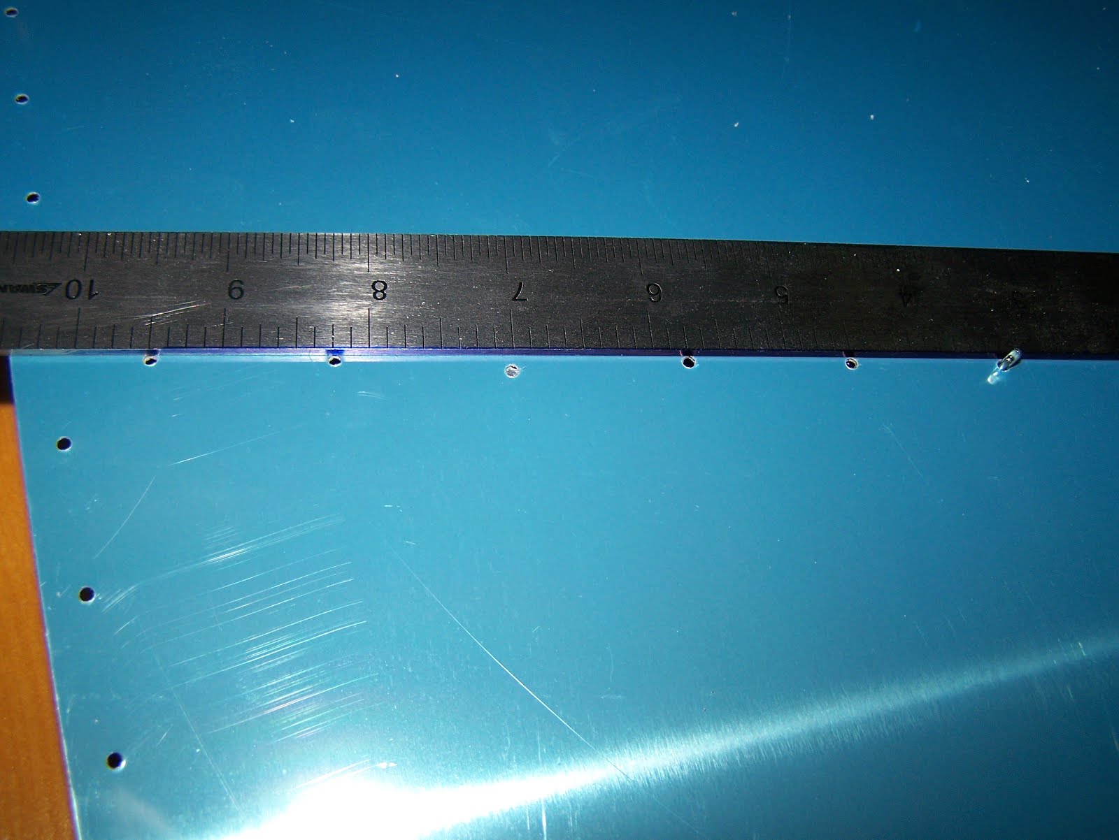
I started match drilling the left skin to the stiffeners when I encountered the following prepunched hole pattern:

You can see clearly that the hole near the 7" mark on the ruler is out of alignment. Here is a shot from the other side:

Unfortunately this is a blocking issue. The hole in the skin does not line up with the hole in the stiffener. I sent an email to Van's with a detailed description of the problem. I am hoping they will send me a new skin with the correct hole pattern. It looks like I'll have to put the left rudder skin aside for now pending what I hear from Van's.
I can try to move on to the rudder skeleton, and my replacement rib for the HS should arrive this week, so I should be able to get back to that.
Time spent: 2 hours (25 total)

I match drilled the stiffeners to the right skin and put everything aside, making sure to bundle and mark the right stiffeners so they do not get mixed up with the left ones.
I started match drilling the left skin to the stiffeners when I encountered the following prepunched hole pattern:
You can see clearly that the hole near the 7" mark on the ruler is out of alignment. Here is a shot from the other side:

Unfortunately this is a blocking issue. The hole in the skin does not line up with the hole in the stiffener. I sent an email to Van's with a detailed description of the problem. I am hoping they will send me a new skin with the correct hole pattern. It looks like I'll have to put the left rudder skin aside for now pending what I hear from Van's.
I can try to move on to the rudder skeleton, and my replacement rib for the HS should arrive this week, so I should be able to get back to that.
Time spent: 2 hours (25 total)
Saturday, May 9, 2009
Finished tapering rudder stiffeners
Finished tapering the rudder stiffeners. Placed the stiffeners on the rudder skins. The forward side of the stiffeners need to be trimmed to length.
Time spent: 30 min (23 hours total)
Time spent: 30 min (23 hours total)
Friday, May 8, 2009
Match drilled VS, cut rudder stiffeners
I match drilled the VS, disassembled it, and put it aside. I will debur, dimple, and countersink the parts along with everything else.
Began cutting the rudder stiffeners. There are 16 in all (8 pieces cut in half) and the ends closest to the rudder's trailing edge need to be tapered.
Time spent: 2 hours (22.5 total)
Began cutting the rudder stiffeners. There are 16 in all (8 pieces cut in half) and the ends closest to the rudder's trailing edge need to be tapered.
Time spent: 2 hours (22.5 total)
HS work and started VS
Good stuff tonight. I finished drilling the left side of the HS, removed the skin, and put the assembly aside. I had to steal some clecoes from the outboard side to finish drilling the inboard ribs.
I don't want to start the right side until my replacement rib arrives (should get here on May 14th), so I put the HS on hold and started work on the VS.
I can't believe how quickly the VS went together compared to the HS. I fluted the ribs and assembled the skeleton.

Then I attached the skin.


It was getting late so I thought I'd stop there. However, I after reading a post on VAF I thought it would be a good time to organize my hardware. I purchased a plastic storage container a long time ago specifically for this.

You can see I've organized the rivets by type, diameter, and length. The pop rivets are just in random order along the top, and I found it nearly impossible to figure out a good organization scheme for the various nuts and bolts that were merely labeled "Misc Empennage Hardware". Oh well, it's still better than looking for hardware in little paper bags.
Time spent: 5 hours (20.5 total)
Thursday, May 7, 2009
Fit left side HS skin
Tonight I made progress fitting the left skin of the HS to the skeleton. The main goal is to match drill the forward spar and the inboard most ribs. I started by match drilling the ribs to the spars, disassembling the pieces, deburring and removing metal chips to ensure a good fit, then reassembling the skeleton. Then I peeled back the plastic from one of the HS skins (which is from this point forward the left skin) and placed it around the skeleton. I then clecoed every other hole.

Then I flipped the part over and clecoed the other side. Here is my technical councelor checking my work:

Once I had the skin clamped down as much as I could, I marked the hole locations on the two most inboard ribs (these ribs are not prepunched), I fluted them, marked the center line, and then clamped the main rib in place to be match drilled. I then match drilled the holes in the forward spar that are not prepunched.

By the time I had finished I had no more 3/32" clecoes left. Looks like I'll be needing some more sooner than later!

Time spent: 1.5 hours (15.5 total)
Tuesday, May 5, 2009
More HS work, and my first oops
Tonight I continued work on the horizontal stabilizer. Stacey helped me flute some ribs, and I started attaching the ribs to the spars. Here are a couple of neat shots of the structure with most of the ribs in place:


I marked and drilled the left side most inboard main rib, and I was fairly satisfied with the result. However, when I marked the corresponding right side rib, I had the part flipped around. The end result is that I have two ribs drilled for the left side. Here is a shot of the correct drilling pattern:

And here is a shot of my oops:

I don't see any way of safely using this part (besides maybe as a spare left side if I screw that part up somehow), so I ordered a new one from Vans. I can keep moving forward with the HS a little while longer, but at some point I'll probably have to put it on hold until the new rib arrives. While I'm waiting I can always move on to the vertical stabilizer.
Time spent: 1 hour (14 total)
Sunday, May 3, 2009
Bandsaw wars and more HS work
Today I set out to purchase a bandsaw. Unfortunately my closest Home Depot was out of stock, so I picked one up at Lowes.
WARNING: Do not buy this product!

The first thing I noticed when I opened the box is that the little fence it comes with was snapped in two pieces. When I did set it up, the side door did not want to close properly, and then when we turned it on, the motor just buzzed and the overload switch tripped. What a POS!!! After about 30 minutes of making sure it wasn't my fault (had I missed something in the setup?) I returned the POS to Lowes and drove to the next closest Home Depot to pick up a Ryobi.

Wow, what a difference! Setup was a snap, no broken parts, and the motor spun up when I flipped the ON switch. What a concept!
With my new toy I went back to work tapering those reinforcement bars:


Using two blocks of wood, a rubber mallet, and a digital level, I put a 6° bend on each side of the reinforcement bars. I finished the bend relief notches in the front HS spar channels with a precision sanding bit in the Dremel, bent the ends of those to 6°, and then clecoed the front HS spar in place.

It almost looks like an airplane part:

I notched the flanges on two of the ribs to fit around the reinforcement bars:

Then I started fluting ribs. Here is a before and after of one of the leading edge ribs:

Time Spent: 4 hours (13 total)
HS spars
Today I disassembled the spars and completed all those steps I skipped yesterday. I polished the rear spar reinforcement bars, matched drilled those in place, enlarged the holes where the main ribs will attach, and match drilled all of the elevator hinge brackets.
After that I moved on to the front spar assembly. I match drilled the two bars of angle to the spar channels. The two reinforcement bars need to be trimmed and then bent to a 6° angle. I was hoping to do that today, but I ran into a little snag. After 15 minutes with the bench grinder and a hand file, this is how far I got:

You can see I did make progress, but I probably have another 15-20 minutes to go just on that corner, and there are eight corners in all. At that rate it will take four hours to trim these parts. I decided to hold off until I can pick up a bandsaw (maybe tomorrow).
So I moved on to the next step which is to notch out some of the spar flange. According to the manual, the spars are the same ones that the RV-8 uses, but need to be modified slightly to fit the RV-7. I had to notch the flanges back to about where the 6° bend will go. I then had to make a relief notch for the bend. You can see the rough teardrop shape of the relief notches in the following photos:


Time Spent: 4 hours (9 total)
Friday, May 1, 2009
Gentlemen... start your engines!
I have actual progress to report tonight. I actually assembled something! It only took me a week!
Before I could get started I needed to pick up a scotch brite wheel for my grinder. I bought something at the local hardware store, but it turned out to be not what I wanted at all. I found an industrial supply store (Abbot Treat Industrial) that carries 3M products and is not far from home. They were super friendly, and they even opened the store up for me when I showed up five minutes after they had already closed. I plan to stop back in soon to shop around - there's lots of neat stuff in there.
Anyways, armed with my new scotch brite wheel, I went to work on the HS-609PP rear spar reinforcement bars. I rouned the ends and rounded the edges that rest against the corner of the rear spars. Then I clecoed the reinforcement bars to the spars.
Why stop there? I then attached the main ribs, final drilled the elevator hinge brackets and attached them, and then I drilled the HS-411BPP bracket to the HS411-APP bracket and the VA-146 bearing. This is the "elevator junction" which will connect to the elevator horns (you'll see).
Why stop there? Once I was done with the rear spar, I started on the front spar. I clecoed both front spar channels to the HS-710 and HS-714 reinforcement angle.
Here are the front and rear spar assemblies so far:


Here is a set of elevator hinge brackets clecoed in place:

Here is the "elevator junction" clecoed in place:

Here are the reinforcement angles clecoed to the front spar channels:

Don't let these pictures fool you. It's not as far along as it might appear. I have done very little match drilling, almost no deburring, and no dimpling or priming. It has a long way to go before I can start driving rivets, but that's ok. It feels great just to make any progress at all.
Time Spent: 2 hours (5 total)
And the winner is...
It's AZKO all the way! Granted the prep time is longer and the chemicals are noxious, but man I'm getting a much better finish with AZKO than I am with the self etching primer. Here are two siffeners from the practice project. The dark gray one in front was primed using the self etching primer and the gold one in back was primed with AZKO. Both pieces were alumiprepped and alodized.

Please excuse the blurry photo, but here you can see the self etchingprimer scratches off easily with a fingernail:

This is one of the reinforcement places. These were the last parts I primed. This is pretty close to what the finish should look like. Very light coat, just enough to make the part that distinctive gold color. I was holding the part by the corners which is why they are not covered well. I still have to put together a chickenwire spray and drying rack.

I'm sure there are as many opinions on the topic as there are builders - and then some. For me, it's the three step Alumiprep, Alodine, AZKO. Sure it may slow down the process a bit, but I can't argue with the finished result. I'll still keep some self etching primer around for the little one-off jobs.
I'm going to try and alter the build process a bit in an attempt to reduce the number of batches I need to prime. I would love to complete the tail kit with only one or two days of priming. That means getting all the subassemblies fitted, dimpled, and deburred before I drive any rivets so that I can prime all of the parts in bigger batches. I'm not positive on the feasibility of this approach, but I'm going to give it a try.
Subscribe to:
Posts (Atom)